Representative Locomotive Features
Introduction
The Sandringham class locomotive is an easily recognisable design whether you as an individual like that design or not. But what are the distinguishing features that make it so? And what of those features that are peculiar to the class and would uniquely identify it.
This breaks down into two categories, that of the aesthetics that would visually identify the locomotive as a B17 and the internal design features.
To be able to get a better understanding of this we need to look at how the B17 design evolved.
DESIGN EVOLUTION OF CLASS B17
The design requirement
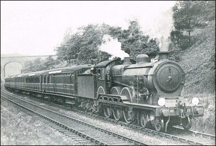 |
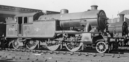
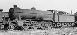
GER Class B12 4-6-0 Introduced 1911 Designed by S.D. Holden Boiler 180 psi 2 Inside Cylinders 6ft. 6in. Driving Wheels Express Passenger |
By the mid-1920s, the power requirements of the GE District (former Great Eastern Railway) were becoming critical. There was a particular shortage of suitable locomotives for hauling express passenger services, which had become heavier (up to 430 tons) with increasing traffic and the introduction of heavier vacuum-braked coaches. Due to the limitations of the GER loading gauge, suitable locomotive types could not be transferred from other parts of the LNER system.
This came to a head immediately after the General Strike (1926), when a shortage of quality coal led to appalling engine performances and the virtual failure of a number of stopping services on the Cambridge and Southend lines. LNER Management quickly ordered Gresley to produce a 4-6-0 design to supplement the existing B12s (pictured above) on the heavier passenger services.
The specification
 |
LNER Class D49 4-4-0 Introduced 1927 Designer H.N. Gresley Boiler 180 psi 3 Cylinders 6ft. 8in Driving Wheels Intermediate Passenger |
The initial specifications were for a three-cylinder 4-6-0, borrowing the cylinder and motion arrangement and the 6’ 8” driving wheels of the D49 4-4-0, with a tractive effort of about 25,000lb and the axle loading restricted to 17 tons. The Doncaster design office had many problems satisfying this specification. The Locomotive Running Department was not satisfied with the resulting drawings, and the contract was handed to the North British Locomotive Co. (NBL.) in December 1927.
The design
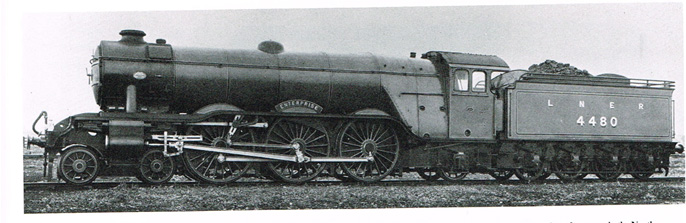 |
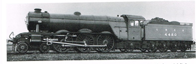
A1 / A3 pacific profile. (6’ 8” driving wheels and raised running board)
The NBL design team used several features from a batch of A1, (A3) Pacifics they had built in 1924. This included the cab, cylinders, and motion which were either copied directly or slightly modified to suit the B17.
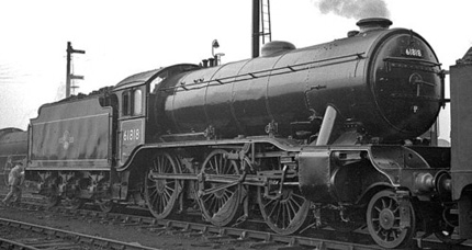 |
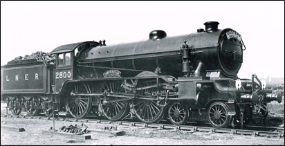
K3 Boiler profile
 |
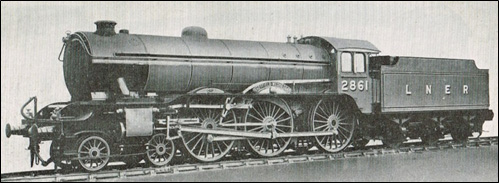
O2 Boiler profile
Most of the boiler design was taken from the LNER class K3 2-6-0 and LNER class O2 2-8-0 designs.
 |
V1 and V3 2-6-2T cranked outside steam pipes
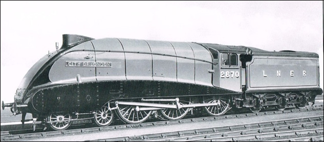 |
A4 Streamlining
In September 1937, Nos. 2859 & 2870 were given A4 -style steamlining for working the "East Anglian" service from Liverpool Street to Norwich. These B17s would be given the classification B17/5. This streamlining was for show only, and served no practical purpose at typical B17 speeds.
 |
| GE Tender |
 |
| LNER tender |
Darlington Works provided drawings for the bogies, and Stratford Works designs for the GE-type 3,700-imperial-gallon (17,000 l; 4,400 US gal), 4-long-ton (4.1 t) tenders.
To summarise
The final B17 aesthetic design borrowed many features from the LNER family of locomotives to negate the need for a totally new design. The cab, cylinders and motion, and the raised running board had all been copied directly, or slightly modified, from the existing A1 (A3) design, the latter to facilitate access for the 6’ 8” driving wheels that were also used on the D49.
The boiler design had a history with the K3 and O2 design and the cranked outside steam pipes were common with the V1 and V3 2-6-2 Tank.
Tender designs were already extant at Stratford for the smaller tender for use on the GE section.
The one (invisible) design peculiarity is the divided drive. It was impossible for all three cylinders to drive the middle coupled axle, so the middle cylinder powered the leading axle and was positioned forward above the front bogie.
Conclusion
So aesthetically, there is not one obvious feature that is peculiar to the B17 design. It was designed in a similar way to the GWR family of locomotives using common parts and designs wherever possible. However, as you can see from the montage below, it is clearly one of the LNER family, and it could be argued that it inherited all the best features from the parental designs at its conception.
B17 PARENTAGE
 |
 |
| A1/A3 | V1 Tank |
 |
 |
 |
| K3 | O2 |