Construction Progress
DESIGN AND MANUFACTURING PROGRESS REPORTS for previous years
2022 2021 2020 2019 2018 pre 2018
DESIGN AND MANUFACTURING PROGRESS REPORTS for 2024
July
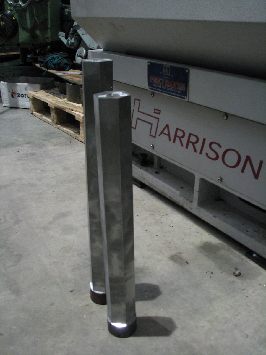
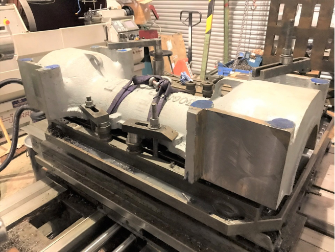
The machining of the six driving wheels continues. With each centre bore hub machined out to size and polished, attention has moved to the Crank Pin bosses; all six have been had this location bored and whilst in situ the centre hub dimensions were accurately measured using a Faro machine. As noted in May, these are needed for finishing of the plain axles; the delivery of these is now keenly awaited, as when received we will have all the components of the Intermediate and Rear Coupled wheelsets. In the meantime, the final machining on the reverse face of each wheel will now be completed, so that each wheel is the required final thickness.
 |
Boring of the Crank Pin Boss. |
| Wheel mounted ready for boring of the Crank Pin Boss. |  |
 |
Wheel and operator, showing the scale of these 6'8" Drivers. |
| Measuring the centre bore hub dimension of a driving wheel. |  |
 |
Viewing the results of the Faro measurements.
Photos by Brian Hall. |
At Shildon, minor components such as spacers are being prepared for the Cannonboxes which are already onsite, and a start is being made on machining the Coupled Axleboxes - these are for the Front Driving wheelset.
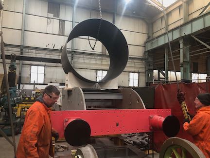
With the Smokebox wrapper in situ on a temporary cradle for the Open Day, other smokebox parts have been progressed. The Smokebox Door is on order from Purdie Dished Products while the manufacturer for the Ring and Seal Groove has been selected and an order being prepared.
Finally, one of the lesser-known tasks under way is to paint the frames in order to protect them from corrosion. This is being carried out professionally by leading specialist in the field of heritage painting, Phil Anderson. Here are a couple of recent shots, including some from unusual angles between the frames. So far, from the bufferbeam to the intermediate driving wheel location has been treated.
 |
 |
 |
| Photos courtesy of Phil Anderson |
May
Machining of the six driving wheels at CTL Seal continues. Last week (on 7th May) Tom Ingall visited and filmed the third wheel having its hub machined. The full video is viewable at https://youtu.be/hwe3vVU1S.
Once all the wheels have their hub machined to the final size, the dimension of each hub can be sent to Railway Wheelsets where the ordered plain axles await this measurement. Once received, we will be in a position to create the two rear Driving Wheelsets, planned for later in the year at South Devon Engineering.
March
As preparations for the Open Day (13th April) proceed, we are glad to report progress on two visually iconic items - the Smokebox and the Bufferbeam.
As noted back last July, the CAD drawings for various Smokebox parts were ready and since had been transformed into manufacturing drawings for both quotes and orders. The first items that has now been received are the Smokebox Wrapper and Liner. These were delivered to our base at CTL Seal in early March. A substantial wooden cradle was made and fitted on Monday 25th March. The same day, the wrapper was hoisted onto the cradle. The Wrapper and Liner are made in an extremely tough steel called Corten B, which is higly resistant to corrosion.
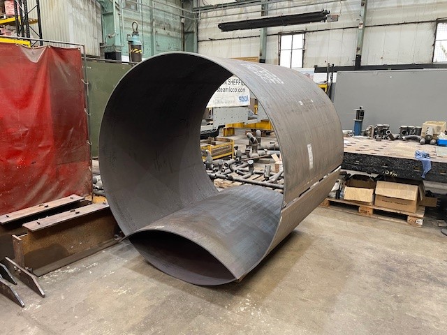 |
The Smokebox Wrapper and Liner delivered by Barnshaws to CTL Seal. | 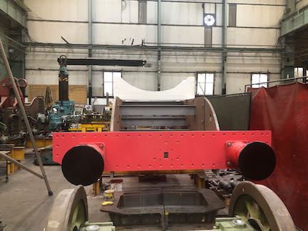 |
View showing the wooden cradle in place, ready for the Smokebox Wrapper to be lowered onto it. |
| The wrapper is now on its way! | 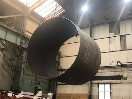 |
Carefully being lowered into place. | 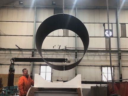 |
 |
In position and also showing the bufferbeam painted in red undercoat. | 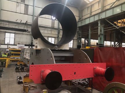 |
In place ready for the Open Day. Photos by John Pearson |
In addition, two buffers have been restored and fitted to the bufferbeam, which is being painted to a high standard and is shown below, magnificent in red gloss with black on the buffer fronts. After the Open Day, the Smokebox wrapper will be removed and the various holes and slots will be made.
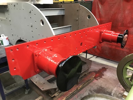 |
Looking very smart, the buffer beam has been painted, showing off the two buffers to good effect. For the Open Day, a surprise is in store! |
Elsewhere, machining is virtually finished on the two Cannon Axleboxes (for the Internediate and Rear Coupled Wheels) up in Shildon and work has started on the Coupled Axleboxes (for the Front Coupled Wheels), whilst at CTL Seal the final machining of the Coupled Wheels, as decribed in November, is due to commence.
February
With the Smokebox manufacturing drawings complete, we have started to procure various components. The first order has been made for the Smokebox Wrapper and liner; discussions are ongoing with supplliers for the door, seal and ring.
DESIGN AND MANUFACTURING PROGRESS REPORTS for 2023
August to November
This has been a time to consolidate several of the items mentioned in the previous months below.
The design activity continues on the Bogie and the Smokebox. The former is now at the point where the bogie axle assembly has been submitted to the Regulator; an order for the casting of the wheels is ready as soon as this is approved. The Smokebox design has progressed such that manufacturing drawings for the Smokebox liner, the door and the ring have been emailed out to potential suppliers and we are is discussion regarding an order.
The Coupled (Driving) wheels, all of which are now at CTL Seal after going through all the Non Disruptive Testing and will soon go through their final machining phase; this comprises the machining of the hub ready for fitting on the plain axles, machining the Crank Pin Hole and the Keyway on all six wheels.
May to July
Smokebox
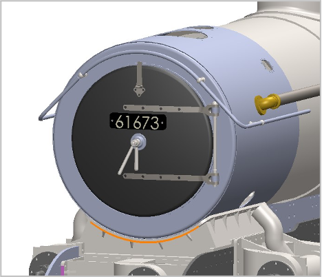
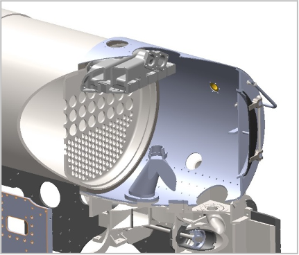
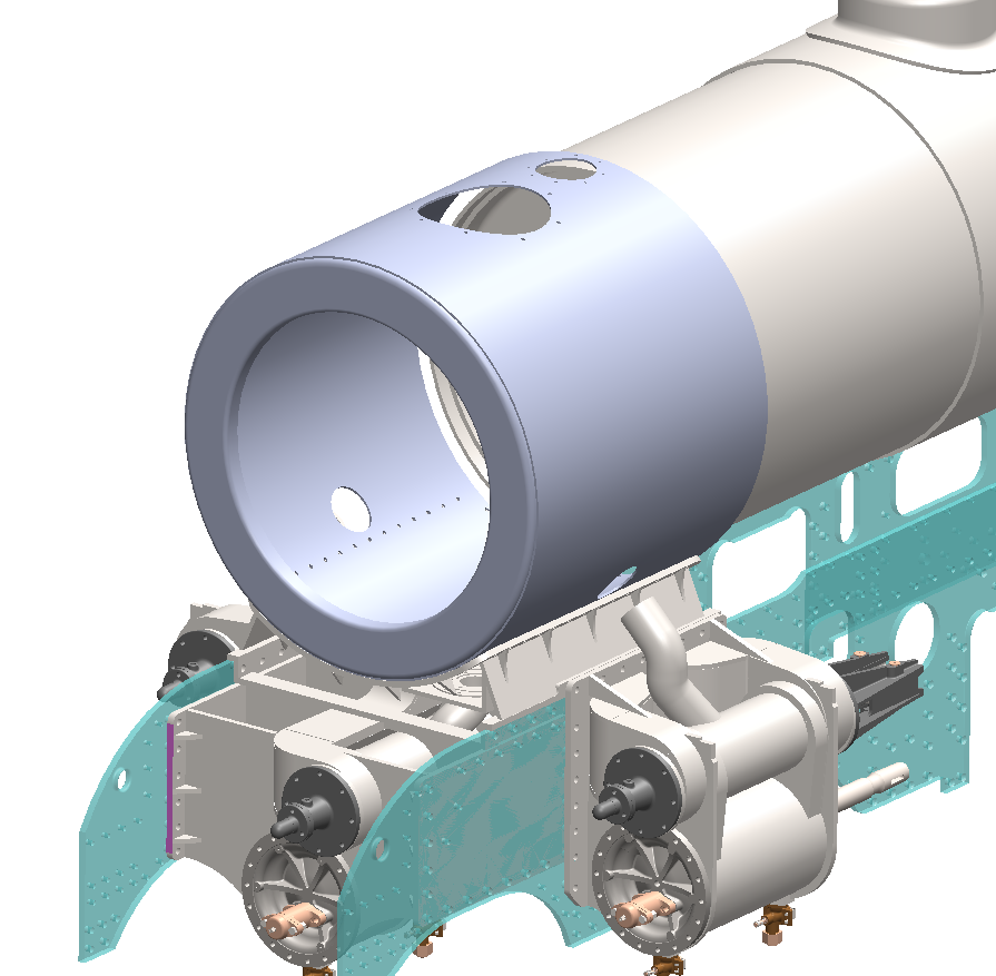
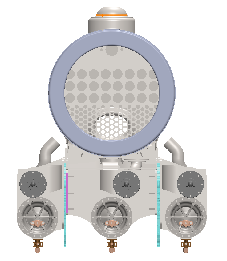
Design work continues to create CAD images from original LNER drawings of the B17 Smokebox General Arrangement from which manufacturing drawings will be created. The alignment of the Smokebox Wrapper and the Doubling Plate (inside) at its base must match the Exhaust Steam ports emerging from the Cylinders via the Saddle to eventually connect to the Blastpipe. Similarly adequate clearance must be assured between the Chimney, Liner and Cowl assembly with respect to the ‘Snifting Valve’ mounted immediately behind the chimney, and also the Superheater Header located on the Smokebox Tubeplate. These items are indicated on the 3D illustrations below. Manufacturing drawings have also been started for the Smokebox Door, Hinge and Chimney including the Liner and Cowl.
 |
 |
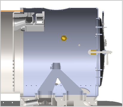 |
| View showing how 61673 will look with all the smokebox components added. | Cutaway view showing the Superheater Header, Tubeplate and Blastpipe. | Side view showing again showing the location of the Superheater, Tubeplate and Blastpipe. |
Bogie Assembly
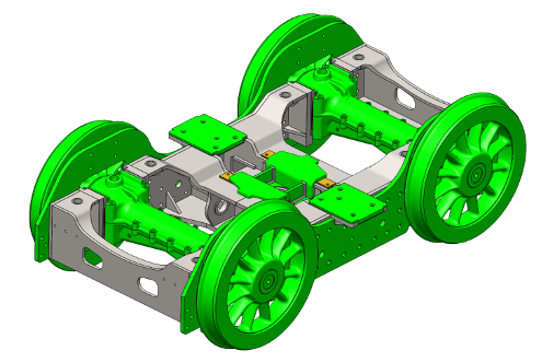
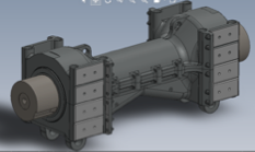
Work continues using CAD techniques to develop the Bogie Assembly using steel fabrications as the basis of producing a stronger and cost effective chassis structure. This method supersedes the original use of castings, bearing in mind that patterns no longer exist for that purpose. This design change will also combine with the introduction of Timken tapered roller bearings and includes a smaller version of the Cannonbox arrangement compared with those associated with the Intermediate and Trailing positions on the main chassis. Patterns for this particular Cannonbox have been kindly loaned to the B17 project by the A1 Steam Locomotive following usage on Tornado and the P2 project.
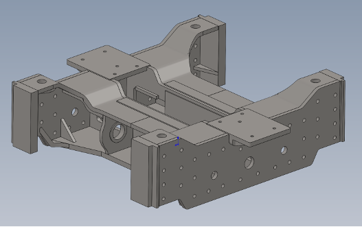
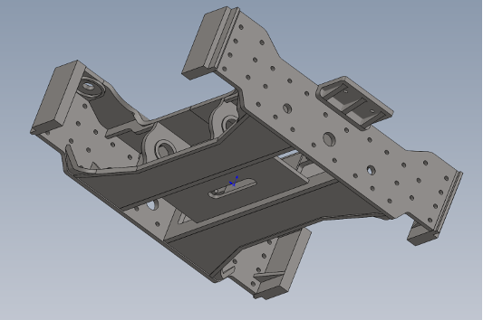
Completed designs of fabricated structures to date are shaded grey on the 3D illustrations shown and represent the Bogie Bottom Centre incl. Side Frames and Cross Stays plus the Slipper Plate, Chassis Template and Side Bearers (all green), to be manufactured from steel plate. For completeness, further items illustrated below consist of the Cannonboxes and 12 Spoke Wheels/Axle sets (green).
 |
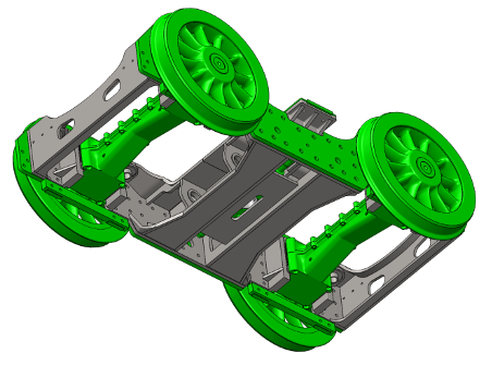 |
| Top view showing Side Bearers, Slipper Plate, and the Chassis template. | Underside view showing Cross Stays and the Bottom Centre inc Side Frame. |
Design work is continuing on the Crosshead, Bogie Top Centre and Pintle, where this latter sub-assembly will eventually be securely fitted to the mainframe structure. A measurement check of fixing hole positions is planned to ensure correct alignment is achieved. Spring details must be also be defined for the Bearing Springs and Side Control Springs.
The initial set of manufacturing drawings for components and sub assemblies highlighted in the illustrations below are currently subject to internal Design Review. Further drawings will be added to complete the full set for the Bogie Assembly. A complete design package will then be submitted with an Engineering Justification to the Independent Rail Authority for their approval.
Finally, we have placed an order with Railway Wheelsets Ltd for the supply of the 2 plain axles for the bogie wheelsets - we already have the wheel pattern made, plus the Timken roller bearings and the Tyre plugs in stock.
Coupled (Driving) Wheels Cannon Axleboxes
The weld attach of the full set of Manganese/Steel Back Plate Liners to the sides of both Cannonboxes was completed successfully at Loughborough and then returned to Shildon for final machining. The joint faces between each top and bottom half have now been machined completely flat and both halves bolted together at the required torque. Machining the long tapered holes to accept tapered bolts has also been completed.
The matching bolts will now be fitted and torque loaded. Machining the locations for each tapered roller bearing and associated spacers inside each Cannonbox is to follow. Once complete, Side Plate Liners will be fitted and secured in position. Detailed measurements will be conducted and recorded at each stage. Completion is planned for September when Final Inspection will be conducted.
April
While we continue the work to create the wheelsets for the main Coupled Driving Wheels, we have opened up two new construction ‘fronts’, starting detailed work on the bogie frames and assemblies, and the Smokebox.
Bogie Frame: The CAD work on the cylinder design has been paused at a suitable point and the consultant is now working on the Bogie Frame design. The first CAD drawings of this are shown here.
 |
 |
Smokebox: Putting the Face on the loco! Work on the CAD version of the existing LNER drawings of the Smokebox including the Smokebox ring, Smokebox door + fittings, Smokebox door hinges, Chimney, Cowl and Liner started at the beginning on April. Shown below are the first two CAD drawing just received – much detail still has to be added before they are usable for both regulatory approval and for the issuing of RFQs.
 |
 |
Driving Wheel Suspension System: With the successful funding of the ‘Spring in my Step’ appeal, discussions have recommenced with our preferred supplier to valid the original quote, whilst submitting the design changes to the regulatory authority; necessary because of changes from the original designs due to increased spring axle weights from the original drawings.
Finally, the refurbishment of two of our buffers. An order has been placed with CWE Ltd. nr Scunthorpe to refurbish these two. Once complete, the bufferbeam can be painted red and the buffers fitted; with the smokebox attached above, the locomotive will start to come alive!
March
Work continues at a pace on the two Cannon Axleboxes, the various Hornblock Plate Liners and the six Hornblocks in a number of locations.
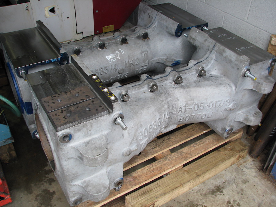 |
Photo shows the two Cannon Axleboxes finish machined and assembled (stage 1) at Daniela Works, Shildon. Seen in this photo are the lugs to take the hardened steel bushes - see the last photo in this series. |
| Finish machining of the surface of Manganese Steel Plates after welding to the Mild Steel backplate at North View Engineering Services (NVES). | 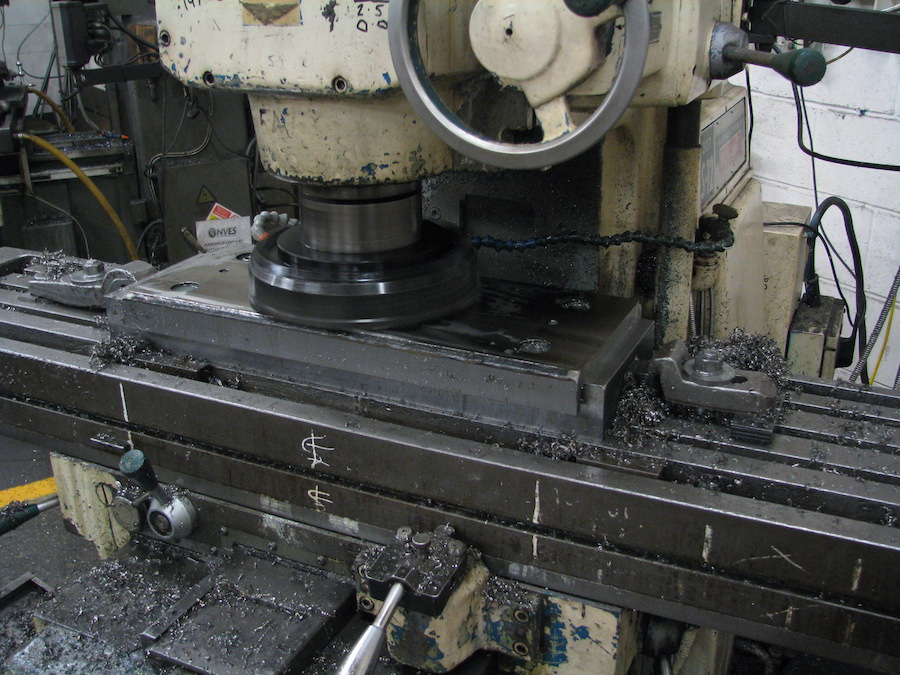 |
 |
The finished Hornblock Plate Liners at NVES. |
| Heat treated tapered bolts with a ground finish will be used during the final Cannon Axlebox assembly to firmly secure the whole structure. | 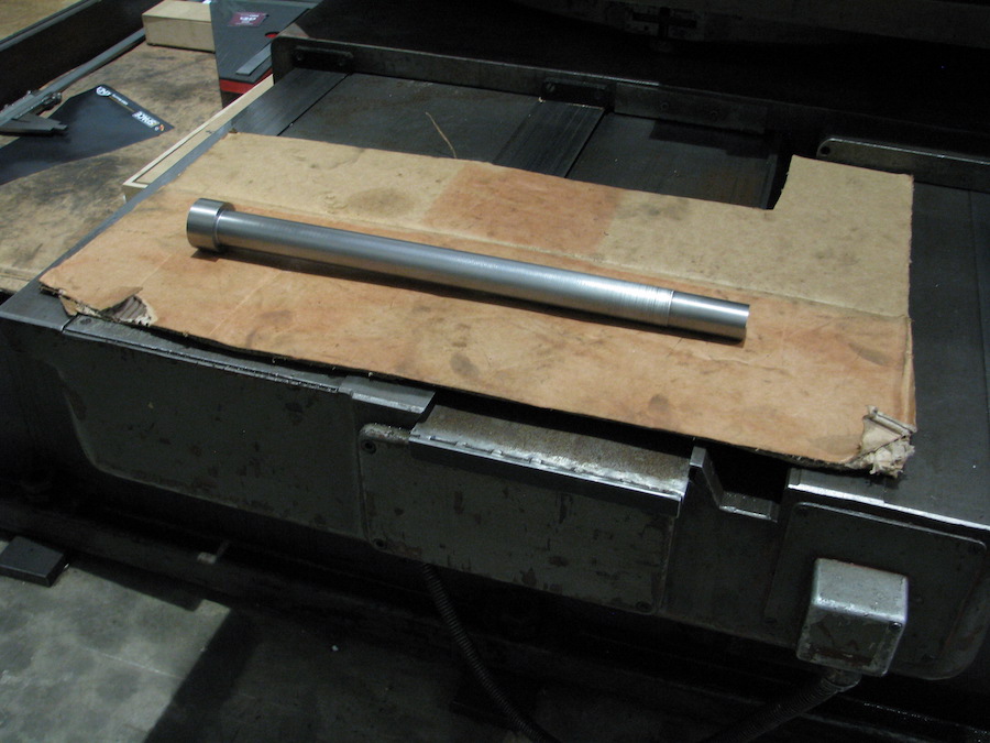 |
 |
Homemade castellated nuts are made from round bar - hexagon bar of the required size and type of material is no longer made, so have been produced specifically for this job. |
| Hardened steel bushes will be fitted into each pair of cast lugs located on the underside of the bottom Cannon Axlebox castings. The finished bushes are heat treated. Both inner and outer diameters will be ground to precise size and pressed into position, using cryogenic techniques. These bushes provide the suspension interface between the end of each axle and the main leaf spring assembly. |  |
February
Cannonbox Assemblies
Some of the main work during the past few months has concentrated on the Cannon axlebox assemblies. The photographs that follow give an indication of how the machining has been carried out at Daniela Works in Shildon.
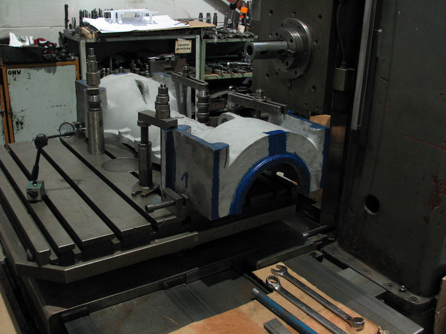 |
The Cannonbox set up for initial machining. |
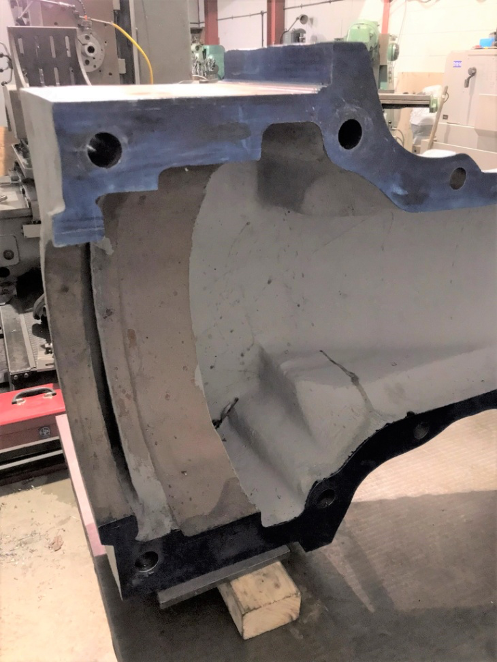
|
Initial machining of joint faces between the top and bottom halves of each casting. The Inside detail at end of the casting shown. The locations for the Timken tapered roller bearings and special spacers will be machined later. |
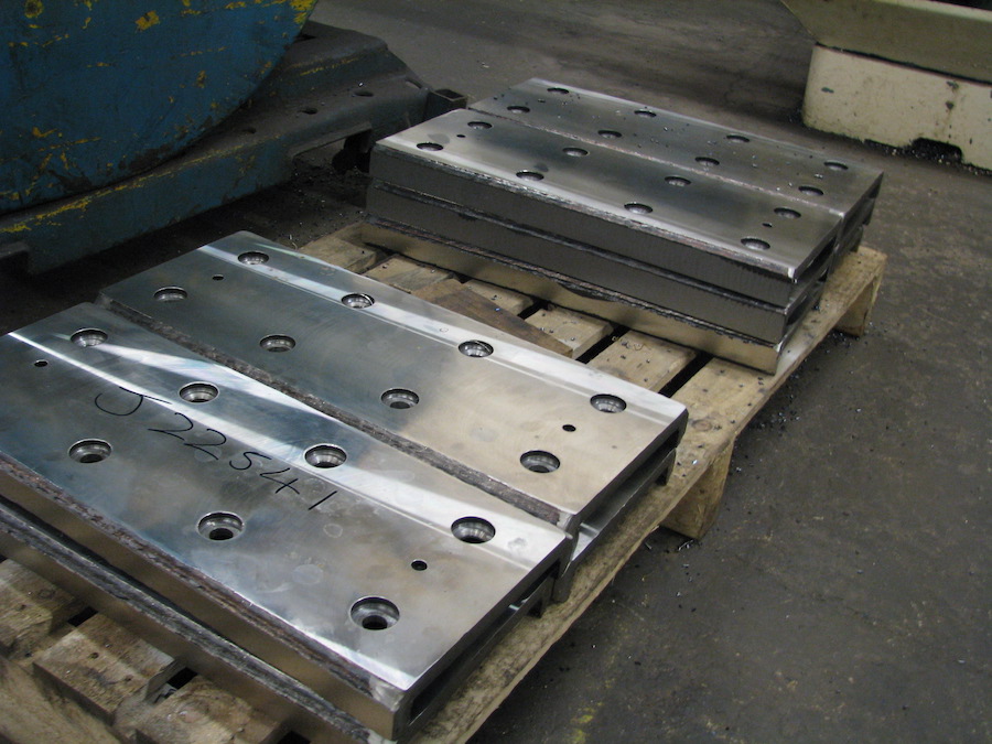
 |
 |
Machining surfaces ready for welding on the manganese steel backplate liners. These will be welded in position on the top and bottom halves prior to final machining of joint faces / internal bores.
|
|
What the final product will look like!
|
|
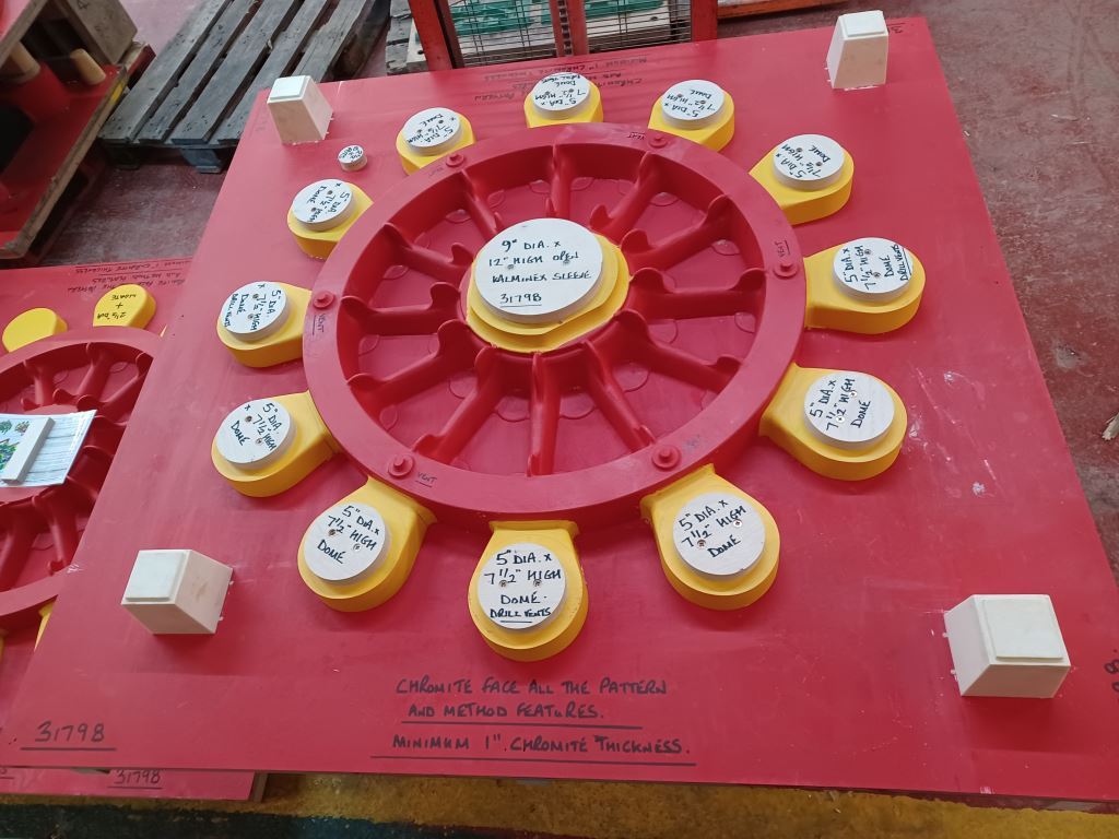
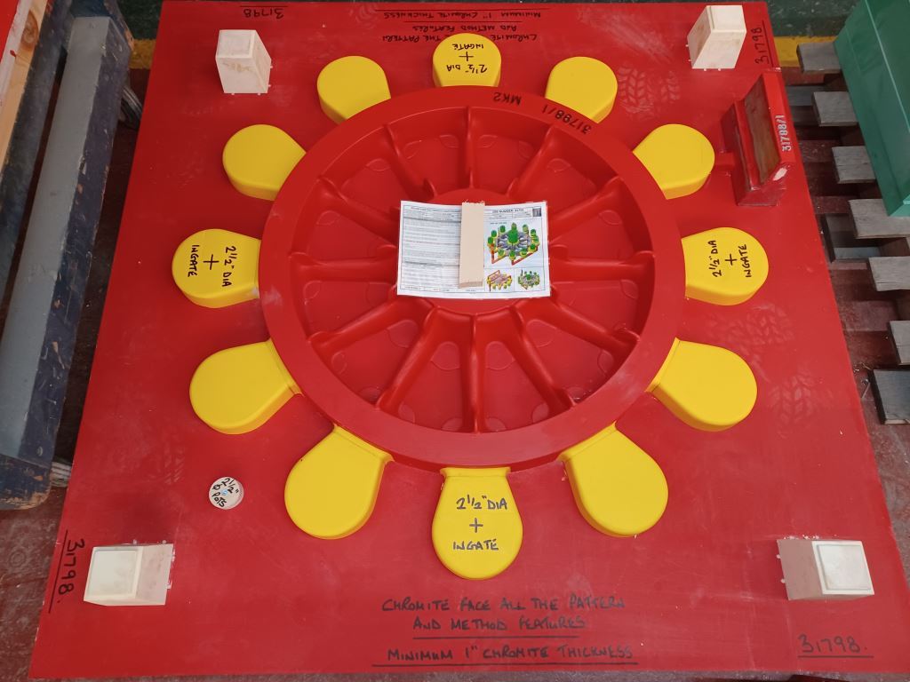
Our 12 spoke bogie wheel pattern has been completed by William Cook in record time - the order was only placed in December after the decison was made to go for the 12 spoke NER Darlington practice, rather than the 10 spoke Doncaster one. The pictures below show both sides of the finished pattern. An order for the casting of the four bogie wheels will be placed when we have regulator approval.
 |
 |